MOHR'S CIRCLE

Because of the many terms and signs involved, and the many calculations required in the computation of the principal stresses and the maximum shear stress, there is a rather high probability of error. Using the graphic aid Mohr's circle helps to minimize errors and gives a better "feel" for the stress condition at the point of interest.
After Mohr's circle is constructed, it can be used for the following:
1. Finding the maximum and minimum principal stresses and the directions in which they act.
2. Finding the maximum shear stresses and the orientation of the planes on which they act.
3. Finding the value of the normal stresses that act on the planes where the maximum shear stresses act.
4. Finding the values of the normal and shear stresses that act on an element with any orientation.
The data needed to construct Mohr's circle are, of course, the same as those needed to compute the preceding values, because the graphical approach is an exact analogy to the computations.
If the normal and shear stresses that act on any two mutually perpendicular planes of an element are known, the circle can be constructed and any of items 1 through 4 can be found.
Mohr's circle is actually a plot of the combinations of normal and shearing stress that exist on a stress element for all possible angles of orientation of the element. This method is particularly valuable in experimental stress analysis work because the results obtained from many types of standard strain gage instrumentation techniques give the necessary inputs for the creation of Mohr's circle. (See Reference 1.) When the principal stresses and the maximum shear stress are known, the complete design and analysis can be done, using the various theories of failure discussed in Chapter 5.
Procedure for Constructing Mohr's Circle
1. Perform the stress analysis to determine the magnitudes and directions of the normal and shear stresses acting at the point of interest.
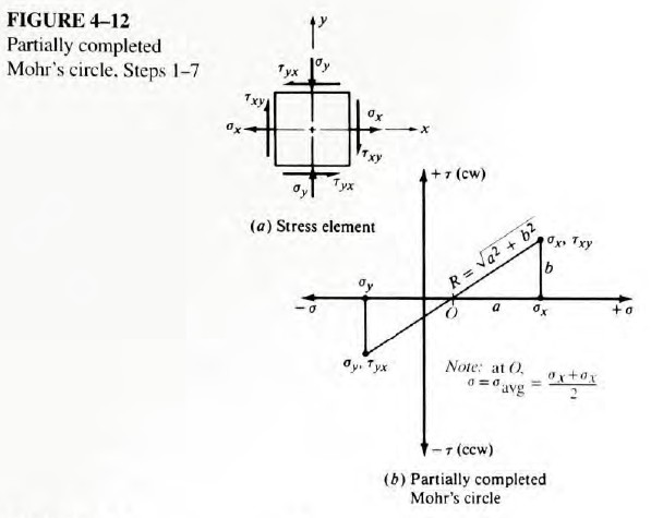
2. Draw the stress element at the point of interest as shown in Figure 4-12(a). Normal stresses on any two mutually perpendicular planes are drawn with tensile stresses positive - projecting outward from the element. Compressive stresses are negative - directed inward on the face. Note that the resultants of all normal stresses acting in the chosen directions are plotted. Shear stresses are considered to be positive if they tend to rotate the element in a clockwise (cw) direction, and negative otherwise.
Note that on the stress element illustrated, σx is positive, σy is negative, τxy is positive, and τyx is negative. This assignment is arbitrary for the purpose of illustration. In general, any combination of positive and negative values could exist.
3. Refer to Figure 4-12(b). Set up a rectangular coordinate system in which the positive horizontal axis represents positive (tensile) normal stresses, and the positive vertical axis represents positive (clockwise) shear stresses. Thus, the plane created will be referred to as the σ-τ plane.
4. Plot points on the σ-τ plane corresponding to the stresses acting on the faces of the stress element. If the element is drawn in the x-y plane, the two points to be plotted are σx, τxy and σy, τyx .
5. Draw the line connecting the two points.
6. The resulting line crosses the σ-axis at the center of Mohr's circle at the average of the two applied normal stresses, where
The center of Mohr's circle is called O in Figure 4-12.
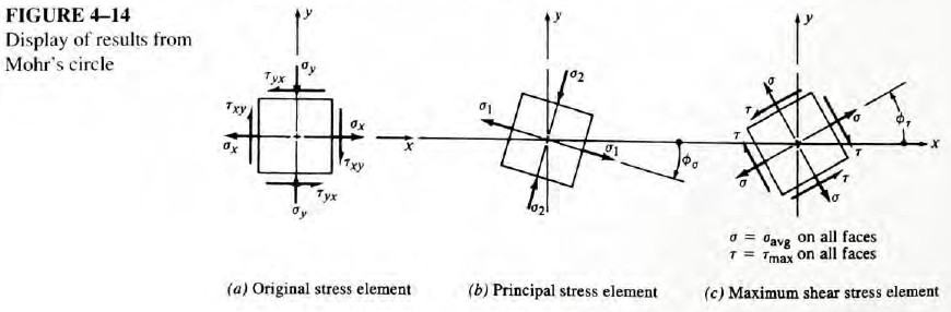
7. Note in Figure 4-12 that a right triangle has been formed, having the sides a, b, and R, where
By inspection, we can see that
The point labeled O is at a distance of σx - a from the origin of the coordinate system. We can now proceed with the construction of the circle.
8. Draw the complete circle with the center at O and a radius of R, as shown in Figure 4-13
9. The point where the circle crosses the σ-axis at the right gives the value of the maximum principal stress, σ1. Note that σ1 = σavg + R.
10. The point where the circle crosses the σ-axis at the left gives the minimum principal stress, σ2. Note that σ2 = σavg - R.
11. The coordinates of the top of the circle give the maximum shear stress and the average normal stress that act on the element having the maximum shear stress. Note that τmax = R.
Note: The following steps relate to determining the angles of inclination of the principal stress element and the maximum shear stress element in relation to the original x-axis. It is important to realize that angles on Mohr's circle are actually double the true angles. Refer to Figure 4-13; the line from O through the first point plotted, σx, τxy, represents the original x-axis, as noted in the figure. The line from O through the point σy, τyx, represents the original y-axis. Of course, on the original element, these axes are 90° apart, not 180°, illustrating the double-angle feature of Mohr's circle. Having made this observation, we can continue with the development of the process.
12. The angle 2ϕσ, is measured from the x-axis on the circle to the σ-axis. Note that
It is also important to note the direction from the x-axis to the σ-axis (clockwise or counterclockwise). This is necessary for representing the relation of the principal stress element to the original stress element properly.
13. The angle from the x-axis on the circle to the vertical line through τmax gives 2ϕ. From the geometry of the circle, in the example shown, we can see that
Other combinations of the initial stresses will result in different relationships between 2ϕσ and 2ϕτ. The specific geometry on the circle should be used each time. See Example Problems 4-3 to 4-8 that follow this section.
Again it is important to note the direction from the x-axis to the τmax-axis for use in orienting the maximum shear stress element. You should also note that the σ-axis and the τmax-axis are always 90° apart on the circle and therefore 45° apart on the actual element.
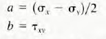
14. The final step in the process of using Mohr's circle is to draw the resulting stress elements in their proper relation to the original element, as shown in Figure 4-14.